TM 5-6350-280-10
1.15.3 Monitor Area Status Screen. The Monitor Area Status Screen (figure 1-6) displays information about the status
of the AMG and is divided into two areas. It indicates the status of the eight modules and the alarm condition of the
modules. It indicates the status of the tamper switches of the CMA and power status of the UPS. It also indicates the
status of the printer and print buffer. The Monitor Area Status Screen is selected to acknowledge alarms or maintenance
actions that occur in the MONITOR section of the system summary. After selecting the Monitor Area Status Screen, the
only action required to acknowledge status changes is pressing <Fl> and <F2> to reset cleared alarms.
1.15.3.1 Module Status Block. The module status block is located on the upper left hand side of the screen. The
module status block is divided into three columns. The first column provides the associated module number. The
second column provides the status of the module and is either "ON" or "off". The third column indicates either an alarm
(ALM) or is blank. When the alarm can be reset, the ALM is displayed in lower case letters.
1.15.3.2 UPS and Printer Status Block. The UPS and printer status block is located at the upper right hand side of the
screen. It is divided into four columns. The first column lists three items. The three items are the UPS, Printer and Print
Buffer. The second column shows the status of the item listed in the first column. The status for the UPS is either
"BATTERY" or "AC". The status for the printer is "ENABLED" "DISABLED" or "NOT RESP". The status for the PNT
(printer) BUFFER is either "OK", "NEAR FULL", "FULL" or "DATA LOST". The third column provides fault information,
"YES" for a fault and "NO" for no fault. The fourth column provides maintenance information. When maintenance is
required or being performed, "YES" appears in this column. When the printer is functional, "NO" appears in this column.
1.15.3.3 Converter Multiplexer Assembly Status Block. The CMA status block is located on the lower right hand side
of the screen. It indicates that the CMA has been opened and is controlled by an interlock change in the CMA. When
the CMA has been opened, an alarm occurs and this box displays the word "TAMPER" on a red background with white
text. If the CMA is closed or the tamper switch is in a maintenance position, the "TAMPER" is changed to lower case
"tamper". The tamper alarm is reset by pressing <F2>.
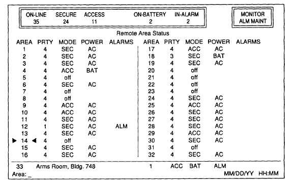
Figure 1-7. Remote Area Status Screen (Typical).
1-11