TM 5-6350-280-10
Table 2-1. UPS Controls and Indicators (continued).
Item
Number
Description
Function
4
AC INPUT FAIL ALARM
Provides error signal to CMA.
.05 AMP MAX
5
AC LINE INPUT Indicator
When illuminated, indicates ac power available for
UPS.
6
OFF INVERTER ON Switch
Removes ac input from the inverter.
7
INV OUTPUT Indicator
When illuminated, indicates power is available for
CMA and computer.
2.1.2 Controls and Indicators CMA. The CMA has no operator controls or indicators.
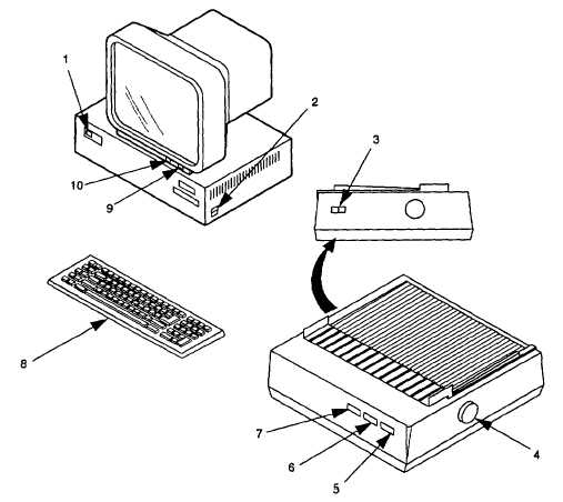
Figure 2-2. Computer Controls and Indicators (Typical).
2.1.3 Controls and Indicators IBM-PC/AT Compatible Computer. The computer (figure 2-2) provides the operational
controls for the AMG. The controls and indicators for a typical computer are listed with a description in table 2-2. Refer
to commercial manuals provided with the computer for a more detailed description and location. The computer, under the
control of the application software, selects the display screens and operational modes as determined by the associated
function key (figure 2-3). The two modes of operation for the AMG are the Secure Mode and Setup Mode. The Secure
Mode is used by the operator and the Setup Mode is used by designated personnel.
2-3